USB DataPump Technical Overview
Everything you need to know about MCCI’s USB DataPump
The architecture of the MCCI USB DataPump® USB Device Stack is explained in the following sections:
- Device Architecture. An overview of and introduction to USB device architecture.
- Design Flow. The steps you must follow to design a device using the MCCI USB DataPump.
- DataPump Device Model. How the MCCI USB DataPump represents a USB device using its internal data structures.
- DataPump Device Operations. How applications use the MCCI USB DataPump to move data and handle control events.
- Protocols and Device Classes. How the DataPump represents USB Device Classes in an abstract and portable form using software modules called “protocols.”
- Implementing Custom Protocols. What’s involved if you need to do a special-purpose protocol.
- Implementation Details. More background information on the USB DataPump.
- Porting the MCCI USB DataPump to a New Platform. What’s involved if your device isn’t already supported.
Sample code showing how to use the MCCI USB DataPump to implement a loopback protocol for bulk or isochronous endpoints is part of the USB DataPump evaluation kit, available from MCCI.
Device Architecture
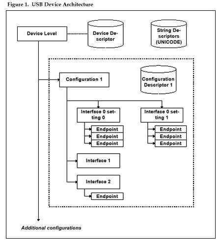
All USB devices follow a standard structural architecture, outlined in chapter 9 of the USB core specification.
- A device is composed of one or more configurations; only one configuration can be selected at a time. That configuration is called the active configuration. Each configuration within a device is identified by a unique numerical index, which is its configuration number. Configuration number 0 is a special default configuration. When the default configuration is selected, the device is not operational; bus-powered devices in the default configuration must obey special power restrictions.
- Structurally, each configuration is in turn composed of one or more interfaces. All the interfaces in a given configuration are available if the configuration is selected. Interfaces are normally used to represent a single function of a multi-function device. However, in communications devices with multiple logical data circuits, one interface is normally used for each logical data circuit. Each interface is identified by a unique numerical index, which is its interface number.
- Functionally, a configuration is composed of one or more functions. Each function corresponds to a specific behavior of the device. For example, a camera/cell phone might present two functions to the host via USB: a modem for access to the internet, and a mass-storage device for transferring JPEG image files from the phone to the PC. Each function consists of one or more interfaces. Functions may be represented implicitly by the interface descriptors, or explicitly using Interface Association Descriptors.
- Each interface, in turn, has one or more alternate settings. Just as only one configuration can be selected in a device at a given time, only one alternate setting can be selected in a given interface at a given time. We call the selected alternate-setting the active interface setting, or just the active interface. Each alternate setting for a given interface is identified by a unique numerical index, also called the alternate interface setting. For each interface, alternate interface zero is the default setting for that interface.
- Each alternate setting assigns certain properties to endpoints, which are the fundamental addressable units on the USB bus.
- Because endpoints are hardware objects, and endpoint settings will change based on the current configuration and alternate settings, USB literature commonly calls the combination of an endpoint and its settings a pipe. A pipe is active whenever its alternate setting and configuration are selected by the host. Similarly, an endpoint is active whenever one of its associated pipes is active. Multiple pipes might use the same physical endpoint, but within a given configuration and alternate settings, an endpoint can only be associated with one active pipe at any given time.
- For device control purposes, every device has a dedicated default pipe, which is always associated with endpoint zero of the device.
The exact structure of the device is represented to the host via the USB device descriptor and configuration descriptors. The host uses this information to load the appropriate device drivers and to determine how to route control messages to the appropriate object within the device.
An Engineering Change Notice (ECN) to the USB 2.0 specification further adds flexibility in defining multi-function devices. As before, each device contains one or more functions. Each function is in turn made up of one or more interfaces. Now, however, the device designer may indicate how interfaces are to be grouped into function using one or more Interface Association Descriptors (IAD). Operating systems use the information in the IAD to help them understand the mapping of interfaces to functions on multi-function devices and to load the appropriate driver for the function. Prior to this ECN, the operating system might need to be updated in order to be able to handle new kinds of multi-function devices. The IAD mechanism provides a generic, technology-neutral means of solving this problem. The designer must still put all the class-specific information in the class descriptors that are defined by the device classes for each specification, and must follow certain rules laid out by the ECN.
Control messages are always sent via the default pipe on endpoint zero. These messages are then routed to one of four different layers in the device:
- The device as a whole. Messages at this layer are used for configuration and to ask the device about its properties.
- An active interface or interface set. Messages at this layer are used to select the active interface setting and to control the operation of the active interface. These messages are addressed using the interface number.
- An active endpoint. Messages at this layer are used to clear error conditions on the endpoint or to perform protocol-specific operations.
- Some “other” (unspecified) location. None of the above.
Of these destinations, only the first three are commonly used.
Even if the IAD mechanism is being used, control messages are still routed via the structural elements (interface or endpoint). There is no way to send a message to a function, other than to send a message to one of its interfaces or endpoints.
In addition, provisions are made for devices to carry natural-language descriptive text, which the host system can present to the user even if the host system doesn’t recognize the device. This text can appear in many different languages, as chosen by the designer. Unfortunately, the text must be prepared in Unicode, in the byte order used by Intel systems, which can make it a little awkward to prepare. However, MCCI provides a tool that makes it easy to prepare these strings, even if the target compiler for the device doesn’t support UNICODE in Intel byte order.
Figure 1 is a schematic diagram showing many of these features.
USB Data Transport Methods
The USB specification defines four kinds of endpoints, each of which has its own link-level protocol. A given physical endpoint might change types, depending on which configuration and alternate interface is selected. However, once the host selects a configuration and alternate interface settings, the type of the endpoint is fixed until the host changes the configuration.
The four endpoint types are:
- Control. Control endpoints use a transaction-oriented protocol. The host sends a setup packet, identifying the operation to be performed. Then the host either transmits additional data packets to the device or requests response data packets from the device, as selected by a flag bit in the packet. Endpoint zero of every USB device is permanently configured as a control endpoint. Control-endpoint data transfers are interlocked and positively acknowledged. Control endpoints are inherently bi-directional.
- Bulk. Bulk endpoints are used to transport data that is not time critical. Data delivery is reliable; packets are delivered in order, and the rate of the sender is automatically matched to the rate of the receiver. However, USB does not guarantee how quickly bulk data will be moved, and it is moved only when there is no time-critical data to be moved.
- Isochronous. Isochronous endpoints are used to transport data that is time critical, and which is useless if it is delivered late. Data delivery is best effort; packets are delivered in order, but packets that cannot be delivered on time are discarded. The receiver is expected to be able to somehow substitute “reasonable” data if packets are dropped. The receiver must be able to keep up with the offered data rate, or data will be discarded. When the host computer opens an isochronous device, the required USB bandwidth for any isochronous endpoints will be allocated to that device. Isochronous endpoints were intended to be used to transport audio or video data, for which missing data is not as bad as late data. Despite this, some devices use isochronous endpoints to transport normal data. In this case, the device and the host driver have to agree on a protocol on top of the basic isochronous protocols, to provide rate matching and error recovery.
- Interrupt. Interrupt endpoints are used to transport time-sensitive data with more error checking than is available for isochronous endpoints. In the USB 1.0 specification, Interrupt endpoints were only defined for device-to-host transfers. In the USB 1.1 specification, interrupt endpoints were made symmetrical, so there are also host-to-device interrupt endpoints. Interrupt endpoints are intended to be used to transport asynchronous information. Like isochronous endpoints, bandwidth is assigned to interrupt endpoints, guaranteeing a certain minimum transfer rate. However Interrupt endpoints take much less bandwidth than isochronous endpoints, at the cost of longer latency.
Design Flow
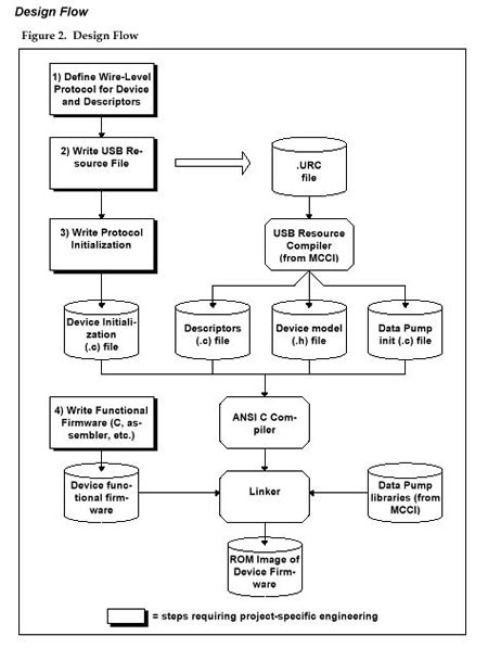
The MCCI USB DataPump was designed with a particular design process in mind.
- You start by specifying how the device will appear “on the wire.” You must specify the following information:
- The descriptors
- The device class specifications to be followed
- Any custom commands or protocols that are to be used
- The endpoints that are to be assigned to specific functions
At the end of this process, you will have all the information you need to verify that the silicon you want to use will do the job. You will also be able to create a prototype USB resource file that describes your device.
- Next, you create the USB resource file (a “URC file”). This file contains, in a high-level format, the descriptors that are needed to represent the device to the host. This file therefore describes the endpoints, interface settings, device class, and so forth. It also contains the information needed to create any string descriptors that the OEM wishes to include.
- Once you have described the peripheral, the next step is to use USBRC, the MCCI USB resource compiler, to generate three files. This process is normally done automatically by the MCCI build system. The following files are created:
- A C code file containing statements that initialize images of all the descriptors in binary form, as an array of chars. UNICODE strings are automatically converted as part of this process.
- A C header (.h) file, containing information (number of endpoints, etc.) and a data structure that models the device. This file is automatically generated and does not need to be edited.
- A C code (.c) file, containing all the code needed to initialize the data structures at runtime to match the description given to the host.
With these three pieces, and linking with the MCCI USB DataPump libraries, the MCCI USB DataPump can automatically support all the USB 1.0/1.1/2.0/3.0 chapter 9 commands, with no additional programming.
- Next, you must create a simple initialization function that attaches any protocols you need onto the USB interface.
- Finally, you write the application code that calls the “top edge” of the protocols according to the protocol APIs.
Although the process has several steps, you do not need to become a USB expert in order to use the DataPump. Using the MCCI USB DataPump and the supplied loopback protocol, MCCI’s customers have demonstrated functionality on their prototype boards within a matter of days, with no prior USB experience.
DataPump Device Model
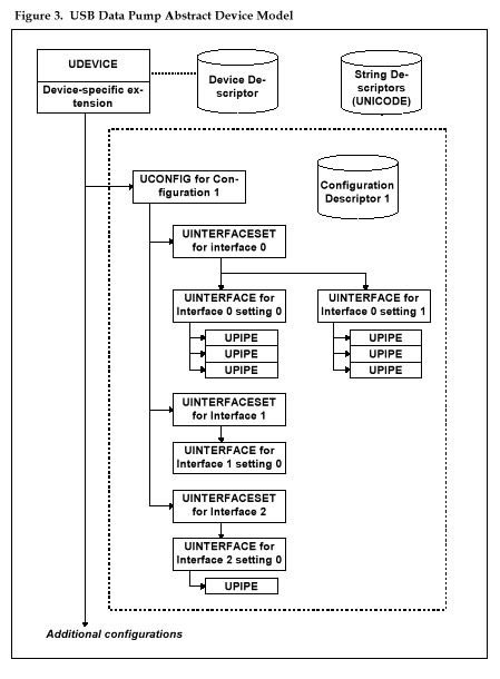
The DataPump USB device stack models a given device as a tree.
- At the root of the tree is a structure representing the USB device, the “UDEVICE.“
- Under the root is a collection of structures, representing each possible configuration; each structure is called a “UCONFIG.” The UDEVICE contains a pointer to the collection of UCONFIGs, and also to the active UCONFIG. The UDEVICE also contains pointers to the tables of descriptors associated with the device.
- Under each UCONFIG is a collection of structures, one for each interface. The DataPump calls these structures UINTERFACESETs, because each one is a collection (“set”) of alternate settings.
- Under each UINTERFACESET is a collection of structures, one for each alternate setting for this interface. (Even alternate setting zero, the default, is treated as an alternate setting.) Each structure is called a UINTERFACE. Each UINTERFACESET contains a pointer to the collection of UINTERFACEs, and also a pointer to the active UINTERFACE within that collection.
- Under each UINTERFACE is a collection of structures, one for each endpoint associated with the alternate setting. These structures are called UPIPEs.
- Each UPIPE contains information about the desired mode for the hardware endpoint in the alternate setting, based on information provided in the “.URC” file. In addition, each UPIPE points to a UENDPOINT structure that models the hardware resources for that endpoint.
- UENDPOINTs are abstract data structures that contain two kinds of information: information used by the portable code (for queuing and control) and information used by the hardware-specific code. Normally, UENDPOINT is treated as the base type for the actual structure that is used by the hardware-dependent layers.
For example, the port of the DataPump for the Synopsys DesignWare USB 2.0 device controller declares an USBPUMP_ENDPOINT_DWCHSOTG structure that represents a UENDPOINT, with additional, hardware-specific information appended to it. So a structure, representing an endpoint, will be viewed in two ways: as a UENDPOINT by the portable code and as a USBPUMP_ENDPOINT_DWCHSOTG by the Synopsys-specific code.
Figure 3 is a schematic of these data structures.
DataPump Device Operations
The USB DataPump API has two fundamental interfaces that are used by applications or protocol modules.
- Data Transfer. Applications transfer data to or from the host in a very traditional way, by issuing data transfer requests. (This is sometimes called an “active” API because the application actively calls the DataPump to cause data transfers to occur.) The basic DataPump interface is asynchronous and non-blocking. An application prepares a transfer request, called a UBUFQE (short for “buffer queue element”), which contains the following information:
- the UPIPE to be used for the transfer
- a description of the buffer of data to be transferred
- some flags, which control the fine details of how the information is to be moved
- a pointer to a function to be called when the operation finishes
The client protocol code calls UsbPipeQueue() to submit the UBUFQE. UsbPipeQueue links the UBUFQE into the queue for the endpoint associated with the pipe, performs any initialization required, and returns to the caller.
Later, when the data has been transferred (transmitted or received), the USB DataPump calls the application’s call-back function to notify the application that the transfer is finished.
- Control. USB control operations operate differently. Instead of the application calling the DataPump directly, applications or protocol modules register event-processing functions with the DataPump. (This is sometimes called a “passive” API because the application passively waits to be called whenever events occur.) The DataPump allows multiple event-processing functions to be registered. In addition, event-processing functions are associated with specific levels in the device tree; the DataPump automatically demultiplexes events and delivers them only to the appropriate level.
There are two general classes of USB events:
- Events which result from chapter 9 processing are processed by the core DataPump. Notifications are then issued to the affected levels of the device tree. Examples of these events include suspend, resume, bus reset, configuration selection, and interface setting selection. If the events in this class have no significance to the device firmware outside the DataPump, you need not provide event handling for them; the USB DataPump will handle them appropriately on its own. Many chapter 9 events are handled entirely by the DataPump without notification to the protocols. These events include getting descriptors, clearing features, and so forth.
- Default-pipe operations that are beyond the scope of chapter 9 are passed to the appropriate level of the device tree for processing. If the event functions supplied by the application coded do not handle the operation, the DataPump sends an error indication back to the host, and aborts the operation.
Both kinds of events are handled by the same basic mechanism.
Protocols and Device Classes
As mentioned previously, the “chapter 9 commands” are those commands defined by the core USB specification as being required for any USB peripheral. However, chapter 9 compliance is not enough; you still have to define how to use USB to control and activate your device.
The core specification defines a general-purpose transport protocol. The device designer builds upon the general protocol to implement more specific functions. Because designing a protocol can be tricky, and in order to allow similar devices to share drivers, the USB Implementers Forum (USB-IF) has defined a number of standard protocols that can be used as the basis for your design. For example, modems often follow the Communication Device Class (CDC) specification as an additional protocol layer added on top of chapter 9.
For some devices there is no adequate protocol defined by USB-IF. In that case, the USB specification allows you to define a vendor-specific protocol. Although this means you must provide your own drivers, this gives you much more flexibility. It can even help you reduce the cost of your device.
For example, RS-232 ports are not supported very well by the CDC specification. MCCI has defined a vendor-specific protocol and protocol extensions to allow RS-232 to be handled either as an extension to the CDC spec (allowing drivers to be shared) or as a purely proprietary protocol (to reduce the cost of the device).
If you are implementing a custom protocol, the DataPump includes a “Vendor Specific Class” protocol module. This module takes care of all the details of interfacing to the DataPump, and exports a simple read/write/IOCTL API to be used by your application-specific code.
Standard Protocols Supported by MCCI
The following protocols are supported directly by the DataPump:
- Communication Device Class Abstract Control Model modem (CDC ACM)
- CDC Wireless Mobile Communication (WMC) Abstract Control Model modem (WMC ACM)
- WMC Object Exchange
- WMC Device Management
- Mass Storage Bulk-Only Transport with ATAPI command set
- Human Interface Device (HID)
- CDC Ethernet Control Model (ECM)
- CDC Ethernet Emulation Model (EEM)
- CDC Network Control Model (NCM)
- Microsoft Remote NDIS
- CDC Mobile Broadband Interface Model (MBIM)
- MCCI Virtual Serial Port protocol
- Device Firmware Update (DFU)
- USB Audio Class 1.0 and 2.0
- USB Video Class 1.1 and 1.5
- Still Image Class
- Vendor-Specific Class
- Picture Transfer Protocol (PTP)
- Media Transfer Protocol (MTP)
- PictBridge
Implementing a Custom Protocol Using the DataPump
Protocols, whether abstract or concrete, are implemented as follows:
- The device initialization function calls a protocol-specific attach function, passing the protocol a pointer to the UINTERFACE or UINTERFACEs that are to be managed by the protocol. This function is normally named XXX_attach(), where “XXX” is the mnemonic for the protocol.
- The protocol initialization function allocates and initializes an instance of a protocol-specific data structure, containing all the information needed to implement that instance of the protocol.
- The instance-data structure normally contains one or more “event nodes.” The protocol initialization function uses these event nodes to register with the DataPump to be called when events occur. For example, if interface 1 is a Communication Class interface, the protocol would attach the event-node to the UINTERFACE structure that models interface 1. The event node contains a pointer to the protocol’s event handler.
- When the host configures the device to use that interface, the protocol event handler will be called. The event handler examines the event code and determines that the interface has been activated. It then does whatever is needed to start up the protocol. If data is to be received from the host, the event handler queues I/O packets to the OUT pipes.
- When the host sends data to the device, the USB DataPump transfers data to the appropriate buffer. When the buffer is full, the DataPump calls the associated completion routine. The USB DataPump then proceeds to the next packet queued for that endpoint. The protocol is entered via the completion entry point (from the UBUFQE), processes the data, and passes the data up to the next layer (if any).
- When the device wishes to send data to the host, it simply prepares a packet and queues it to the endpoint. A completion routine will be called to signal that the data has been shipped to the host so that the device can release or reuse the data buffer.
- When the host sends control packets to the interface, the interface event handler again is called and is allowed to perform whatever protocol-specific handling is required. This may involve further decoding or demultiplexing.
DataPump protocols are very modular and need not duplicate any of the chapter-9 functionality.
USB DataPump Implementation Details
The DataPump is written entirely in ANSI C and has a layered implementation.
- The hardware interface layer is a thin layer that provides OS- and platform-specific services. The DataPump is carefully designed to require very little from the platform.
- The chip interface layer provides the chip-specific code. This allows MCCI to support numerous different chips with the same code base for the bulk of the code.
- The USB DataPump itself implements the chapter-9 functionality: enumeration, configuration, data transportation, and so forth. The DataPump is designed using asynchronous, non-blocking calls, and an I/O queue for each endpoint. This allows event-driven transfers, much in the style of WDM drivers.
- In addition, the DataPump maintains the chapter-9 model of the state of the device. As interfaces and endpoints are “configured” by the host, application-specific event handlers can be called. This provides the hooks for layering multiple independent protocols on top of the DataPump.
Application modules (e.g., the loopback test, the virtual serial port module, or the CDC modem module) are layered on top of the DataPump. This connection is inherently dynamic and reentrant, so multiple instances of a CDC interface can be supported just as easily as a single interface. This is important in USB 3G cell phone applications, as it allows easy implementation of multi-call support.
The USB DataPump is completely portable with respect to target-processor byte order (little-endian vs. big-endian).
Porting the MCCI USB DataPump to a New Platform
Porting involves the following kinds of adaptation:
- compiler
- makefiles
- CPU support
- target hardware platform support
- target OS mappings for USB DataPump primitives
These adaptations normally take about one week of effort altogether, depending on the target environment and the quality of the C compiler, provided that the new platform uses a USB device already supported by MCCI. Because of the emphasis on high performance, writing a new chip driver is more difficult and normally takes about four weeks of effort.